How a torque converter works: interactive cutaway
Set engine and turbine speed on a torque converter cutaway. Watch the stator hold and multiply torque, freewheel, then the lock-up clutch end the slip.
- Drawing
- DT-02.2
- System
- Drivetrain
- Stage
- Transmission, 02 of 05
- Published
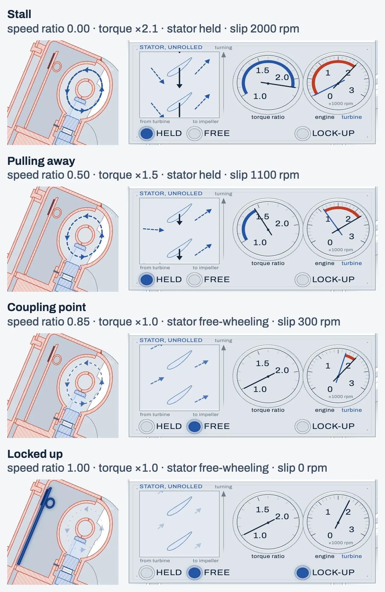
Cutaway of a torque converter on a test bench, its near half cut away so the section shows the oil's ring-shaped room above and below the shaft (cut faces in red). On the engine side, left, a drive motor turns the crankshaft flange and the flexplate, which is bolted to the converter's cover. Inside, from the engine side: the cover, the lock-up piston with its lining and damper springs, the turbine on the engine side of the ring, the impeller on the transmission side joined to the cover, and between the turbine's exit and the impeller's inlet, near the shaft, the stator on a one-way roller clutch on the fixed stator shaft. The turbine hub is splined to the input shaft, which runs out through the pump housing to a brake. Blue arrows show the oil's loop: out of the impeller at the rim, across into the turbine, down it, through the stator and back into the impeller. A console in front shows the stator's vanes unrolled behind a window with the oil arriving and leaving, lamps for the stator held or free-wheeling and for the lock-up, a torque-ratio dial, and a speed dial with an engine needle and a turbine needle, the slip shaded between them.
Example values, not a specification · turning shown at 1/200 speed · lock-up travel drawn about 10× larger
Stall · speed ratio 0.00 · torque ×2.1 · stator held · slip 2000 rpm
What is a torque converter on a car, and why does an automatic transmission have one?
A torque converter is the fluid link between the engine and an automatic transmission, and it does the job a clutch pedal does in a manual: it lets the engine keep running while the car is stopped in gear and takes up the drive smoothly when you pull away.
A manual car does that with a friction clutch that the driver slips by foot. The torque converter does it with oil instead. Its cover is bolted to the engine’s flexplate and spins with the crankshaft; inside, oil carries the engine’s torque to a turbine that drives the transmission. Because the only link is moving oil, the turbine can stand still while the engine idles.
It also does something a clutch can’t: at low speed it multiplies torque, so the car pulls away harder than the engine alone would push it.
From the transmission the drive goes on to the wheels. A Torsen differential is one way the last stage splits it between the two wheels of an axle.
How does a torque converter work?
The engine spins the cover and the impeller welded to it. The impeller throws oil outward, and the oil swirls in the direction of rotation. The turbine takes that swirl out of the oil, which turns the turbine and the transmission shaft it is splined to. The stator redirects the oil back into the impeller, and the loop repeats. Hold the turbine still and open the throttle: that is stall, where the oil loops hardest.
Inside the sealed, oil-filled cover there are three wheels of curved vanes and a clutch:
| Part | Turns with | What it does |
|---|---|---|
| Impeller (pump) | The engine; it is welded to the cover | Throws oil outward and gives it a swirl in the direction of rotation |
| Turbine | The transmission input shaft, splined to it | Takes the swirl out of the oil, and that turns the turbine |
| Stator (reactor) | Nothing while it is held; it sits on a one-way clutch | Turns the oil coming back from the turbine before it re-enters the impeller |
| Lock-up clutch | The turbine; it presses against the cover | Joins turbine and cover so they turn as one |

In a real converter the impeller sits on the transmission side and the turbine on the engine side.
The oil moves in two ways at once. It turns with the cover around the shaft, and it circulates around the doughnut-shaped space: out through the impeller, across into the turbine’s outer edge, down the turbine, through the stator near the center and back into the impeller. Each wheel’s torque comes from how much it changes the swirl of the oil passing through it. The impeller adds swirl, and the turbine takes it out.
How does a torque converter get its fluid?
The converter is sealed and filled with transmission fluid. A hub on its cover drives the transmission’s oil pump, which keeps the converter full and moves the fluid on to the cooler. That pump is a separate part of the transmission, not the impeller inside the cover.
What does the stator do, and how does a torque converter multiply torque?
The turbine’s vanes are strongly curved, so the oil leaves the turbine swirling against the engine’s rotation. Sent straight back into the impeller, that oil would fight it. The stator sits in its way and turns the flow, so the oil enters the impeller already swirling with the rotation.
To turn the flow, the stator has to push on the oil, and the oil pushes back on the stator. A one-way clutch, a roller or sprag type, holds the stator still against that push. Because the three torques inside the converter must balance, the turbine now gets the engine’s torque plus the stator’s: turbine torque = engine torque + stator torque.
Torque multiplication is greatest at stall, when the turbine is held still (the stall torque ratio), typically about 2 to 2.5 times for a passenger car. As the turbine speeds up, the oil leaves it at a different angle and pushes the stator less. At the coupling point, typically when the turbine turns at about 85 to 90% of engine speed, the push is gone. From there the oil meets the backs of the vanes, the one-way clutch lets go, the stator freewheels with the rotation, and the converter becomes a plain fluid coupling with a torque ratio of 1. Drag the turbine up to the coupling point and watch the stator lamp switch from Held to Free.
Multiplying torque does not multiply power. The turbine gets more torque but turns slower, and efficiency is speed ratio times torque ratio. The example below uses the figure’s model, with a stall ratio of 2.1 and a coupling point of 0.85, both chosen inside the typical ranges:
| Turbine speed ÷ engine speed | Torque ratio | Efficiency | Stator |
|---|---|---|---|
| 0 (stall) | 2.10 | 0% | Held |
| 0.2 | 1.84 | 37% | Held |
| 0.4 | 1.58 | 63% | Held |
| 0.6 | 1.32 | 79% | Held |
| 0.85 (coupling point) | 1.00 | 85% | Starts to freewheel |
| Lock-up clutch closed | 1.00 | About 100% (no slip) | Freewheels |
These are example values, not the specification of any converter. At stall all the engine’s power going into the converter turns into heat in the oil.
What is torque converter stall speed, and why does the car creep at idle?
Stall means the turbine is held still, with the car stopped by the brakes or the load. Stall speed is the engine speed the converter allows in that condition, and the term is used three ways:
- Rated stall speed: what a converter is built for. It depends on the converter’s design and on the engine’s torque, so a converter sold as “3,000 rpm” won’t reach that in every car.
- Brake-stall test: in a workshop, the engine speed at full throttle in gear with the brakes on. The test must be short because the oil heats fast.
- Flash stall: the engine speed the converter lets the engine jump to at the start of a hard launch, which also depends on the car’s weight, gearing and tires.
Stock passenger-car stall speeds are typically somewhere around 1,500 to 2,500 rpm. Stall speed is not the moment the stator locks; the stator is held the whole way from stall to the coupling point.
The engine’s load from the converter rises with the square of its speed. At idle the impeller still drags the turbine through the oil, a small torque that the light brake pressure of a stopped car easily overcomes, and that is the creep you feel in Drive. Set the engine to idle with the turbine still and the engine’s tag shows how little torque goes in at idle.
How does a torque converter lock up, and what does the lock-up clutch (TCC) do?
The lock-up clutch locks the converter by pressing a friction piston against the inside of the cover with oil pressure, so the turbine turns with the engine and nothing slips. It is also called the torque converter clutch (TCC) or lockup. Close the lock-up clutch at cruise and the slip drops to zero.
An unlocked converter always slips, roughly 5 to 10% at cruise in the two examples sources give, and that slip turns into heat in the oil. The lock-up piston sits on the turbine side with damper springs, and once it is applied the engine drives the transmission directly, with no slip and no heating of the oil.
Modern transmissions don’t lock it in the lowest gears at low speed, and some slip it on purpose by a small, controlled amount to soak up engine pulses. It must release when you slow to a stop. A lock-up clutch that stays applied stalls the engine like a manual car stopped in gear with the clutch out.
Torque converter vs clutch, fluid coupling and CVT
A torque converter and a manual clutch both let the engine keep running while the car is stopped in gear, but a clutch does it with friction and the driver’s foot, and a converter does it with oil and can also multiply torque. A fluid coupling is a converter without the stator, so it cannot multiply torque.
| How it starts the car | Multiplies torque | |
|---|---|---|
| Torque converter | Oil drives the turbine; the stator adds torque at low speed | Yes, at low speed |
| Fluid coupling | Oil drives the turbine; no stator | No |
| Manual clutch | The driver slips a friction plate | No |
Many CVTs use a torque converter to start the car; some use a start clutch instead. Cars used fluid couplings before converters. The other half of a manual gearbox’s work, changing gears without grinding, is covered in how synchromesh works.
What are the symptoms of a bad or failing torque converter?
The faults that service and training sources describe come in a few groups:
- Stator one-way clutch slipping: no torque multiplication, so the car pulls away sluggishly.
- Stator one-way clutch stuck: poor power at highway speed and very hot fluid.
- Lock-up clutch stuck applied: the engine stalls when you stop.
- Lock-up clutch never applying or slipping: worse fuel use and hotter fluid.
What is torque converter shudder?
Shudder is another common complaint, and carmakers have issued service bulletins for converter shudder and overheating. Shudder isn’t always the converter, though: tires, the driveline or an engine misfire can feel the same.
Do electric cars and hybrids have a torque converter?
Battery-electric cars don’t. An electric motor makes full torque from zero speed, so most use a single reduction gear. Hybrids differ. Toyota’s hybrids use a planetary power-split device and no converter. Some hybrids keep one: Ford’s hybrid 10R80 transmission has a motor mounted on the converter’s shell. ZF’s plug-in hybrid 8-speed replaces the converter with an electric motor and a clutch.
Who invented the torque converter, and when?
Hermann Föttinger, a designer at AG Vulcan in Stettin, patented a hydraulic transmission with driving and driven turbine wheels in 1905. Its first use was at sea, between steam turbines and propellers. Cars got fluid couplings first, and the torque converter reached mass-market cars in the late 1940s. Buick’s Dynaflow went on sale in 1948, and Chevrolet’s Powerglide in 1950.
FAQ
Is a torque converter a clutch?
It does a clutch’s job, letting the engine run while the car stands still, but it works with oil and also multiplies torque. The friction clutch inside it is the lock-up clutch.
Does a torque converter waste fuel?
When it slips, yes: slip turns into heat in the oil. That is why modern transmissions lock it up, or let it slip only slightly, once the car is moving.
How can a torque converter multiply torque without multiplying power?
The turbine gets more torque than the engine puts in, but it turns more slowly, so the power coming out is never more than the power going in. Efficiency is speed ratio times torque ratio, and at stall the output power is zero.
What is the difference between a torque converter and a fluid coupling?
A fluid coupling has only an impeller and a turbine, so it passes on the torque it gets and cannot multiply it. A torque converter adds the stator, which turns the returning oil and gives the turbine more torque at low speed.
Why doesn’t the engine stall at a red light in Drive?
Because the turbine can stand still while the impeller turns. The oil drags the turbine with only a small torque at idle, which the brakes hold.
Sources (18)
- x-engineer.org: How a torque converter works
- Talukder, University of Technology Sydney: torque converter thesis (2014)
- Honda R&D Technical Review 13-1: ultra-flat torque converter (2001)
- Sonnax: stall speed, core selection and more
- Motor magazine: torque converter operation and diagnosis (May 1999)
- AA1Car: Torque converters
- US Patent 7,152,399, Torque converter stator
- US Patent 10,975,960, coupling point and K-factor
- Hebbale et al. (GM): Model based torque converter clutch slip control (SAE 2011-01-0396)
- Voith: Mechanical engineering pioneers at Voith Turbo (Föttinger)
- Ate Up With Motor: Hydra-Matic history, part 2 (Dynaflow and Powerglide)
- GM TechLink: shudder on 8-speed automatics
- Ford TSB 25-2005 (via NHTSA)
- Edmunds: Do electric cars have transmissions?
- Sabin Civil Engineering / Lesics: Torque converter, how does it work? (video)
- EricTheCarGuy: How does a torque converter work? (video)
- Gears Magazine: The Ford 10R80MHT hybrid unit
- Autocar Professional: ZF begins volume production of plug-in hybrid transmission
Where this part sits
Power runs from the engine to the wheels. This part sits at the transmission stage.